
|
|
The external 10 MHz reference input BNC connector, both the shell and center pin, on the rear panel of the instrument is isolated up to ±42 Vpk from chassis. The shell of this BNC connector is isolated from the rest of the instrument. Internal circuitry will attempt to keep the isolated voltage to within ±42 Vpk to chassis. Attempts to float this input beyond ±42 Vpk from chassis may destroy the instrument and cause a hazard that could result in personal injury or death. |
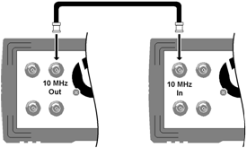
The external timebase reference provides rear panel connectors (10 MHz In and 10 MHz Out) and circuitry to allow synchronization between multiple instruments or to an external 10 MHz clock signal. You can also set the phase offset of the output waveform from the front panel or over the remote interface.
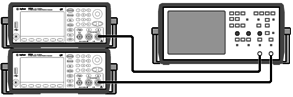
To align the phase of two instruments, use a dual-channel oscilloscope to compare the output signals:


|
|
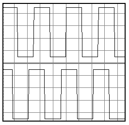
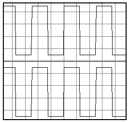
| Out of Phase | Aligned |
You can use Set 0 Phase to set a new zero-phase reference point with the two instruments now aligned.