Delta EVM (Graph)
(differential Error Vector Magnitude) is the Root Mean Square (RMS) of the error vectors, computed and expressed as a percentage of the average power of the stimulus signal.
This metric is also shown at the bottom of Graph traces (when Compensation is enabled) as .
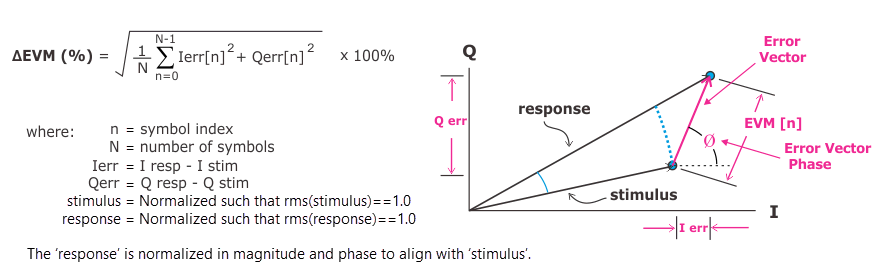
Differential error vector magnitude is defined as the length of the vector which connects a stimulus time-point to the corresponding response time-point. The following graphic shows the calculation of the ΔEVM metric as well as a diagram showing how a single error vector is calculated.
You can view the EVM Error vector magnitude (EVM): A quality metric in digital communication systems. See the EVM metric in the Error Summary Table topic in each demodulator for more information on how EVM is calculated for that modulation format. for each time point using the Delta EVM Time trace.
Delta EVM is only computed when "Compensation" is enabled on the Graph Settings panel for the selected trace. This result is shown at the bottom of some Graph traces (like AM Amplitude Modulation - CW modulation using amplitude variation in proportion to the amplitude of the modulating signal. Usually taken as DSB-LC for commercial broadcast transmissions and DSB-SC for multiplexed systems./AM and AM/PM).
Differential EVM is similar to Standard EVM (demodulated signals) but has some differences when measured in Vector mode:
|
Standard EVM |
Differential EVM |
|---|---|
| Calculated by comparing demodulated points with measured points. |
Calculated by comparing the input to a device to the output from the device. |
|
One-port measurement |
Two-port measurement |
| Interpretation: overall quality metric for transmitter | Interpretation: contribution of individual component (DUT Device under Test: An acronym used to describe some type of electrical apparatus connected to test instrumentation. The apparatus can range from a single component to a complex subsystem such as a mobile phone, base station or MSC.) to transmitter's Standard EVM |
|
Reference signal is demodulated data. |
Reference signal is stimulus signal (actual input to device). |
|
Measured at symbol times only |
Measured at all waveform samples |
|
After baseband filtering |
No baseband filtering |
Post-demod time data
In addition to pre-demod time data (Main Time, Search Time, etc.), the Graph traces allow you to choose post-demod Time traces. For instance, you could choose IQ Ref Time as stimulus and IQ Meas Time as the response data. In this case, the Delta EVM measurement would be comparable to the EVM measurement performed by the demodulator, although the numerical result of calculating EVM with a Graph trace might not exactly match as the demodulator's EVM calculation (for example, in Digital Demod, the two EVM calculations would be numerically equivalent only when = 1 and = Reference RMS).
Instead, you could configure two VSA measurements to demodulate the signal before and after the DUT and compute differential EVM from the IQ Meas traces. In this case, you would set the stimulus/response data to IQ Meas Time from the stimulus measurement and IQ Meas Time from response measurement. This would perform a stimulus-response measurement on time points a receiver would see (only at symbol times, etc.) instead of just measuring the raw performance of the DUT (at all time points, etc. as in Vector mode). Neither method is better; rather, each provides a different view of your DUT's performance.
See Also
Delta EVM Time (trace)