Voltage Measurement: How an Oscilloscope is Connected |
||
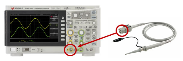
Oscilloscopes are a great tool for measuring the voltage of a signal. Typically, they will display voltage as it changes over time in the form of a waveform on-screen, but many oscilloscopes can also provide a simple voltage measurement. To begin, you should understand how an oscilloscope is connected for a voltage measurement. Step 1: Turn your oscilloscope on and press the “Default Setup” front panel key. Step 2: Plug a probe in to Channel 1. You can use any probe you have, likely a 10:1 or 1:1 passive probe. It’ll be easier if the probe has a clip or other mechanism that prevents you from having to manually hold it to a wire. Step 3: Connect the ground clip to a reliable grounding point.
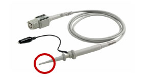
Step 4: Locate your signal and attach your probe to that point.
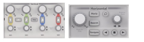
Step 5: Press the “Auto Scale” front panel key to center the signal on screen. You should now see the signal’s voltage as it changes over time, with time on the X-axis and voltage on the Y-axis.
Step 7: Turn on voltage measurements by pushing the “Meas” front panel key. Many oscilloscopes will have some or all of these voltage measurements built-in.
Check out the free 6 Essential Tips for Getting the Most Out of Your Oscilloscope eBook. Learn more about Keysight Oscilloscopes:
|
||